카메라 트리거(Camera Trigger)
카메라 트리거 드라이버는 펄스를 AUX 포트를 사용해서 전송합니다. 드론을 이용해서 조사를 할때 타임스탬프를 가지는 사진, 여러 카메라를 사용하는 시스템의 동기화 혹은 시각-관성(visual-inertial) 네비게이션을 포함한 다양한 어플리케이션에 사용할 수 있습니다.
펄스를 보내는 것 외에도, 메시지의 순서 번호와 타임 스탬프를 포함한 MAVLink 메시지를 publish할 수 있습니다.
트리거 모드
TRIG_MODE 파라미터로 제어되며 지원하는 4가지 다른 모드 :
TRIG_MODE1은 기본 intervalometer입니다.MAV_CMD_DO_TRIGGER_CONTROLMAVLink 명령을 사용해서 활성/비활성화 됩니다. 상세 내용은 command interface 참고하세요.TRIG_MODE2는 intervalometer를 on 상태를 유지합니다.TRIG_MODE3은 거리 기반한 트리거입니다. 설정한 수평 거리를 초과할 때마다 사진을 찍습니다. 사진을 찍는 시간 간격은 triggering interval 설정으로 제한됩니다.TRIG_MODE4는 Mission 모드로 서베이 비행할 때 자동으로 트리거됩니다.
TRIG_MODE 0에서 카메라 트리거가 비활성화됩니다.
만약 처음으로 카메라 트리거 app을 활성화시키는 경우라면,
TRIG_MODE파라미터를 변경한 후에 리부팅을 해야합니다.
트리거 하드웨어 설정
TRIG_PINS 파라미터를 사용해서 트리거에 사용할 AUX 핀을 선택할 수 있습니다. 디폴트는 56이고 이는 트리거가 AUX 5와 AUX 6에서 활성화된다는 뜻입니다.
IMPORTANT : TRIG_PINS을 디폴트 값인 56으로 설정하고 AUX 핀 1, 2, 3, 4를 액츄레이터 출력으로(servos/ESC용으로) 사용할 수 있습니다. 하드웨어 타이머가 처리하는 방식때문에(1234와 56는 서로 다른 그룹으로 2개 타이머로 처리) 카메라 트리거와 FMU 액츄레이터 출력을 동시에 사용할 수 있게하는 유일한 조합입니다. 액츄레이터 출력이 필요하다면 디폴트 TRIG_PINS의 값을 변경하지 마세요
트리거 인터페이스 백엔드
The camera trigger driver supports several backends - each for a specific application, controlled by the TRIG_INTERFACE parameter :
TRIG_INTERFACE1 enables the GPIO interface. The AUX outputs are pulsed high or low (depending on theTRIG_POLARITYparameter) everyTRIG_INTERVALduration. This can be used to trigger most standard machine vision cameras directly. Note that on PX4FMU series hardware (Pixhawk, Pixracer, etc.), the signal level on the AUX pins is 3.3v.TRIG_INTERFACE2 enables the Seagull MAP2 interface. This allows the use of the Seagull MAP2 to interface to a multitude of supported cameras. Pin 1 of the MAP2 should be connected to the lower AUX pin ofTRIG_PINS(therefore, pin 1 to AUX 5 and pin 2 to AUX 6 by default). In this mode, PX4 also supports automatic power control and keep-alive functionalities of Sony Multiport cameras like the QX-1.TRIG_INTERFACE3 enables the MAVLink interface. In this mode, no actual hardware output is used. Only theCAMERA_TRIGGERMAVLink message is sent by the autopilot (by default, if the MAVLink application is inonboardmode. Otherwise, a custom stream will need to be enabled).TRIG_INTERFACE4 enables the generic PWM interface. This allows the use of infrared triggers or servos to trigger your camera.
Other parameters
TRIG_POLARITY- Relevant only while using the GPIO interface. Sets the polarity of the trigger pin. Active high means that the pin is pulled low normally and pulled high on a trigger event. Active low is vice-versa.TRIG_INTERVAL- Defines the time between two consecutive trigger events in milliseconds.TRIG_ACTIVATION_TIME- Defines the time in milliseconds the trigger pin is held in the "active" state before returning to neutral. In PWM modes, the minimum is limited to 40 ms to make sure we always fit an activate pulse into the 50Hz PWM signal.
The full list of parameters pertaining to the camera trigger module can be found on the parameter reference page.
Command interface
TODO : needs updating
The camera trigger driver supports several commands -
MAV_CMD_DO_TRIGGER_CONTROL - Accepted in "command controlled" mode (TRIG_MODE 1).
| Command Parameter | Description |
|---|---|
| Param #1 | Trigger enable/disable (set to 0 for disable, 1 for start) |
| Param #2 | Trigger cycle time in milliseconds (sets the TRIG_INTERVAL parameter. ) |
| Param #3 | Sequence reset (set to 1 to reset image sequence number, 0 to keep current sequence number) |
MAV_CMD_DO_DIGICAM_CONTROL - Accepted in all modes. This is used by the GCS to test-shoot the camera from the user interface. The trigger driver does not yet support all camera control parameters defined by the MAVLink spec.
| Command Parameter | Description |
|---|---|
| Param #5 | Trigger one-shot command (set to 1 to trigger a single image frame) |
MAV_CMD_DO_SET_CAM_TRIGG_DIST - Accepted in "mission controlled" mode (TRIG_MODE 4)
This command is autogenerated during missions to trigger the camera based on survey missions from the GCS.
Testing trigger functionality
On the PX4 console :
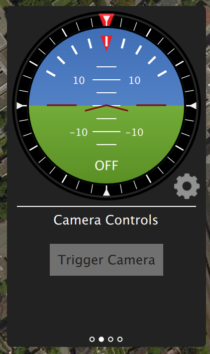
camera_trigger testFrom QGroundControl :
Click on "Trigger Camera" in the main instrument panel. These shots are not logged or counted for geotagging.
Sony QX-1 example (Photogrammetry)
In this example, we will use a Seagull MAP2 trigger cable to interface to a Sony QX-1 and use the setup to create orthomosaics after flying a fully autonomous survey mission.
Trigger settings :
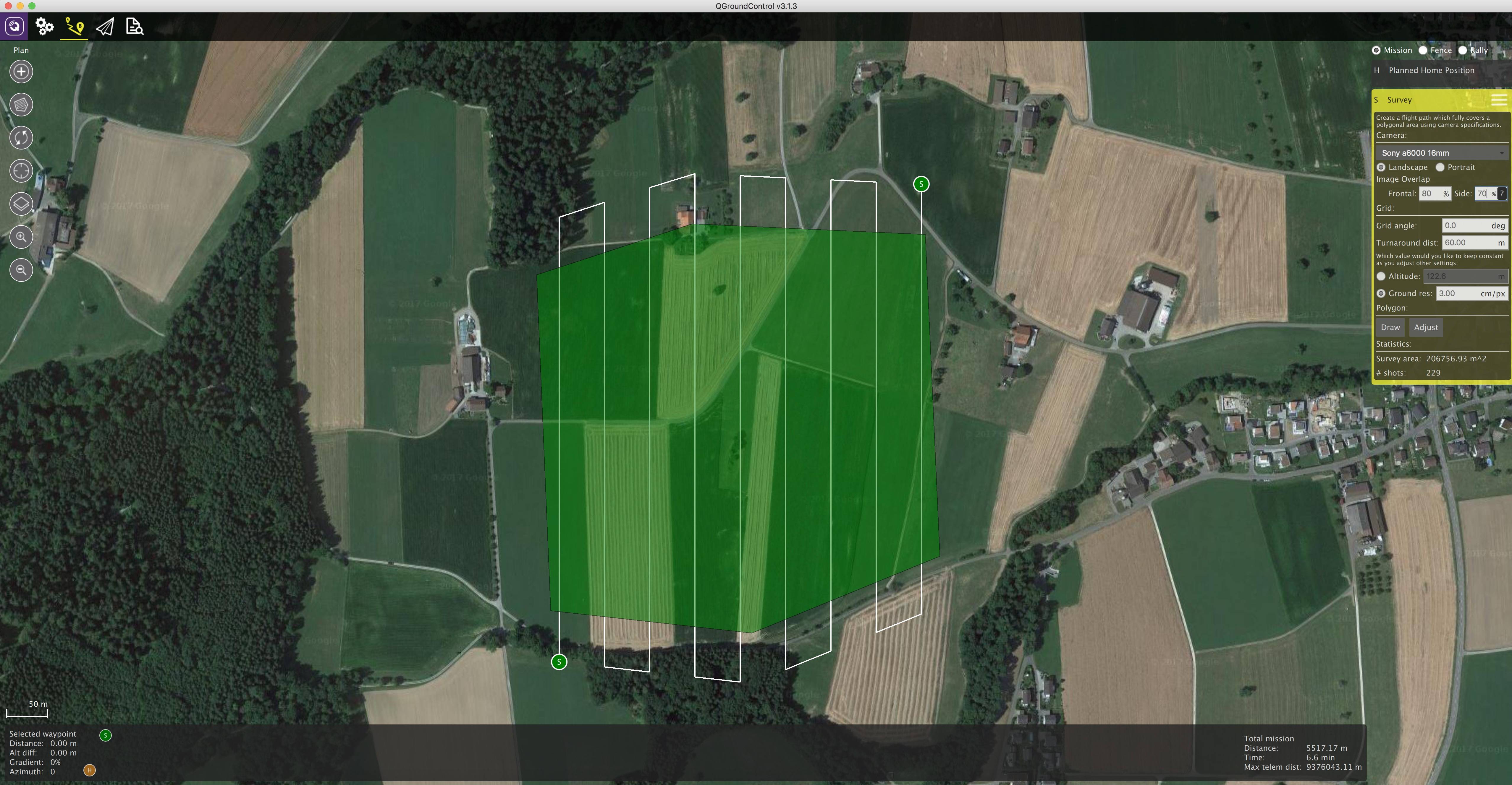
The camera trigger can be configured from QGroundControl's "Camera" page under the settings tab
TRIG_INTERFACE: 2, Seagull MAP2.TRIG_MODE: 4, Mission controlled.
Leave the rest of the parameters at their defaults.
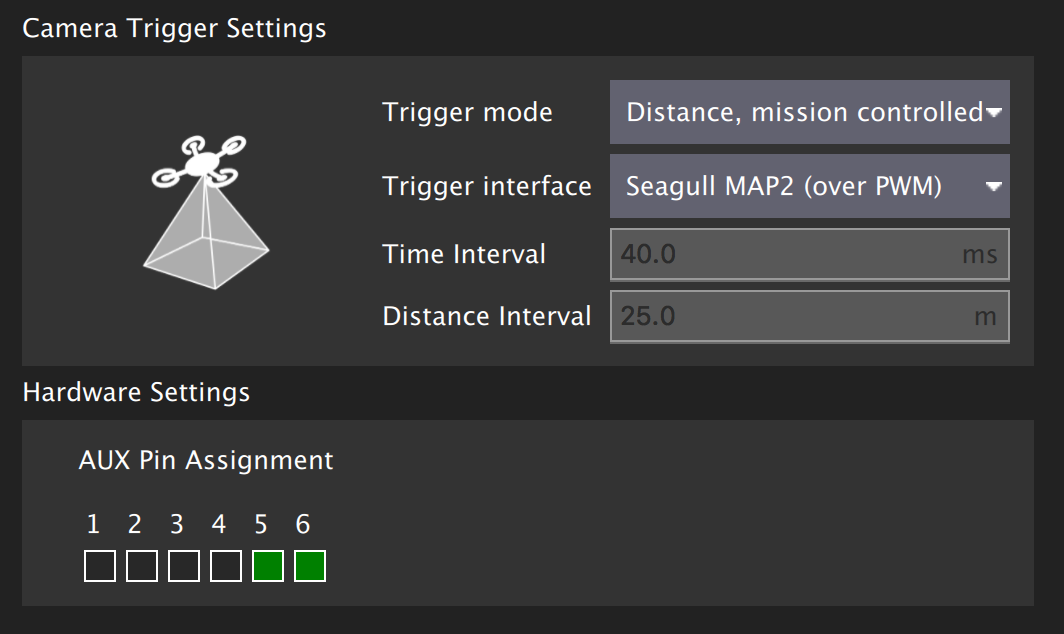
You will need to connect the Seagull MAP2 to the auxiliary/FMU pins on your autopilot. Pin 1 goes to AUX 5, and Pin 2 to AUX 6. The other end of the MAP2 cable will go into the QX-1's "MULTI" port.
Camera configuration :
We use a Sony QX-1 with a 16-50mm f3.5-5.6 lens for this example.
To avoid autofocus and metering lag when the camera is triggered, the following guidelines should be followed :
- Manual focus to infinity
- Set camera to continuous shooting mode
- Manually set exposure and aperture
- ISO should be set as low as possible
- Manual white balance suitable for scene
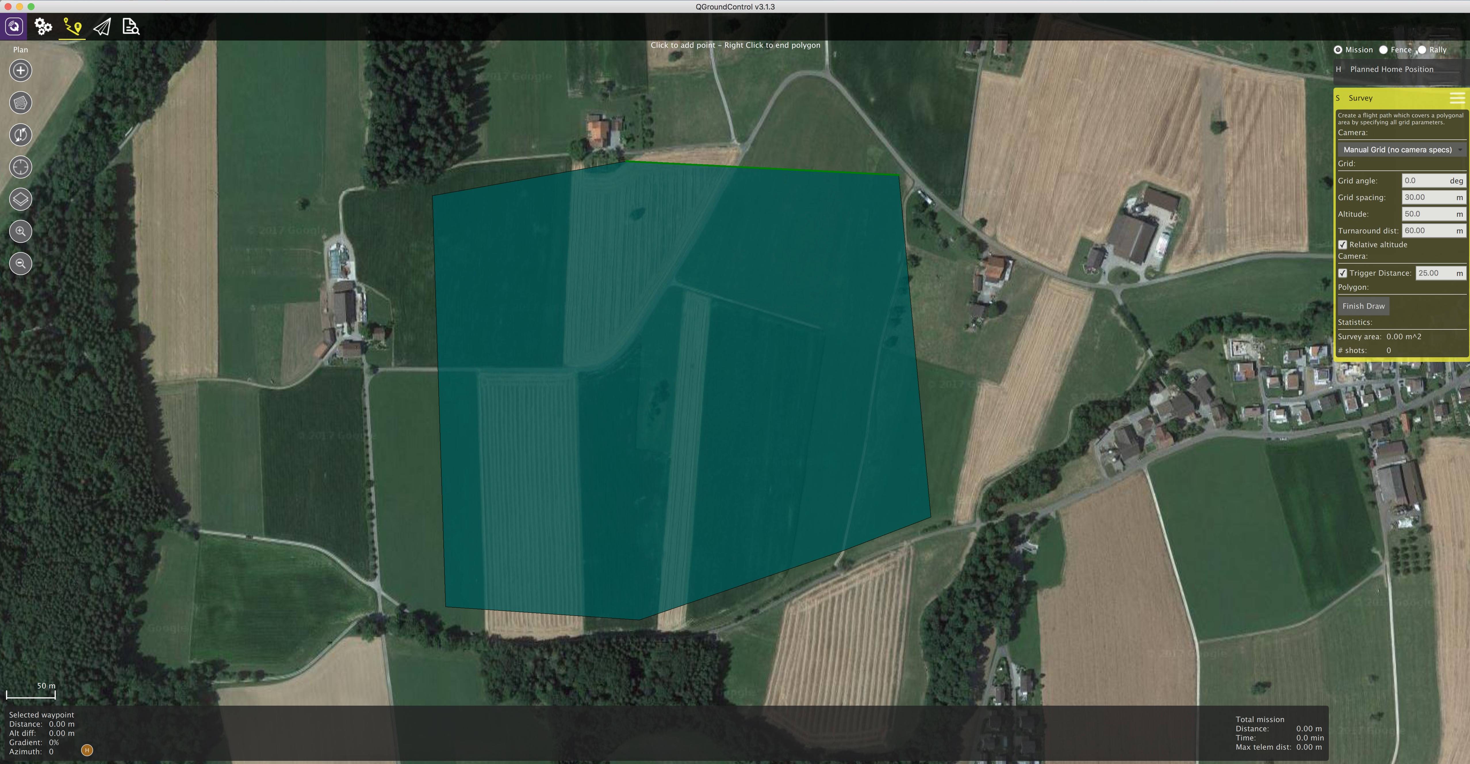
Mission planning :
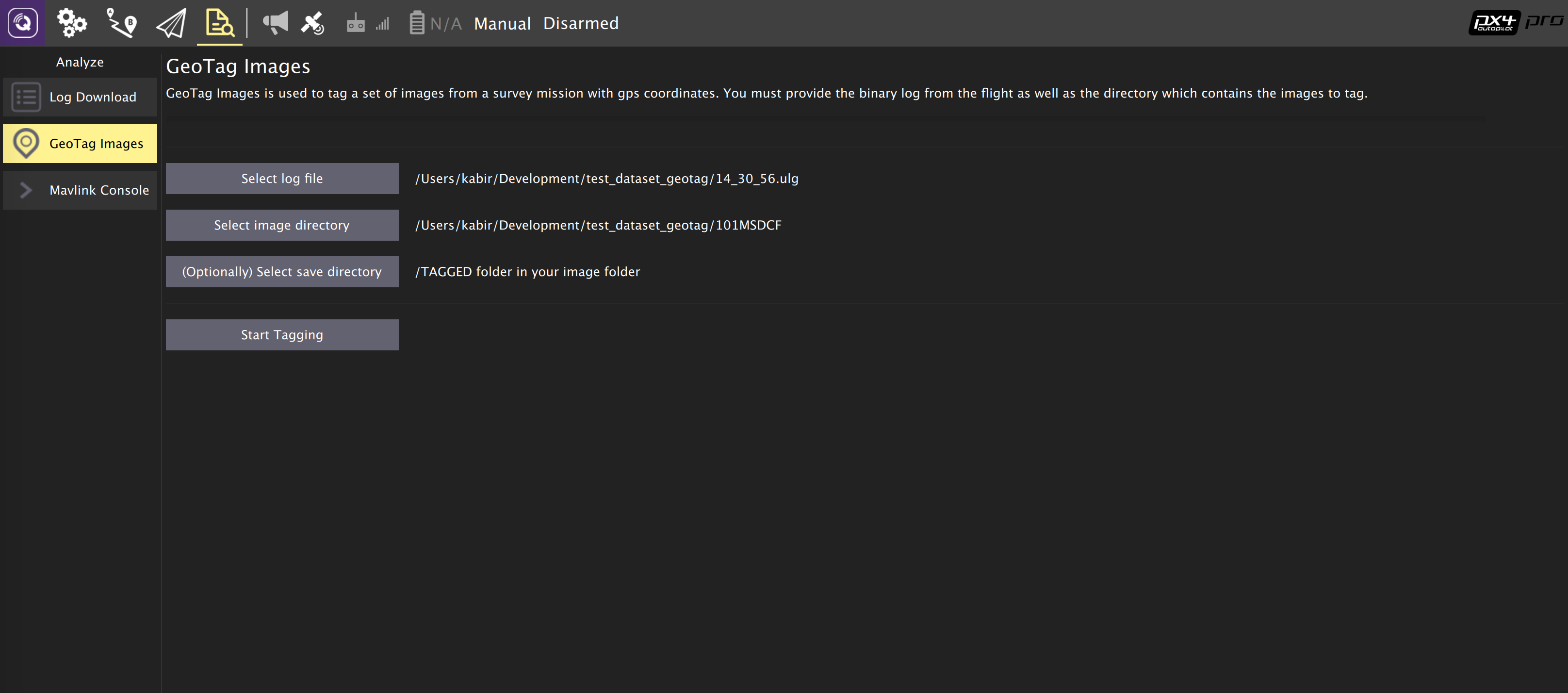
Geotagging :
Download/copy the logfile and images from the flight and point QGroundControl to them. Then click on "Start Tagging".
You can verify the geotagging using a free online service like Pic2Map. Note that Pic2Map is limited to only 40 images.
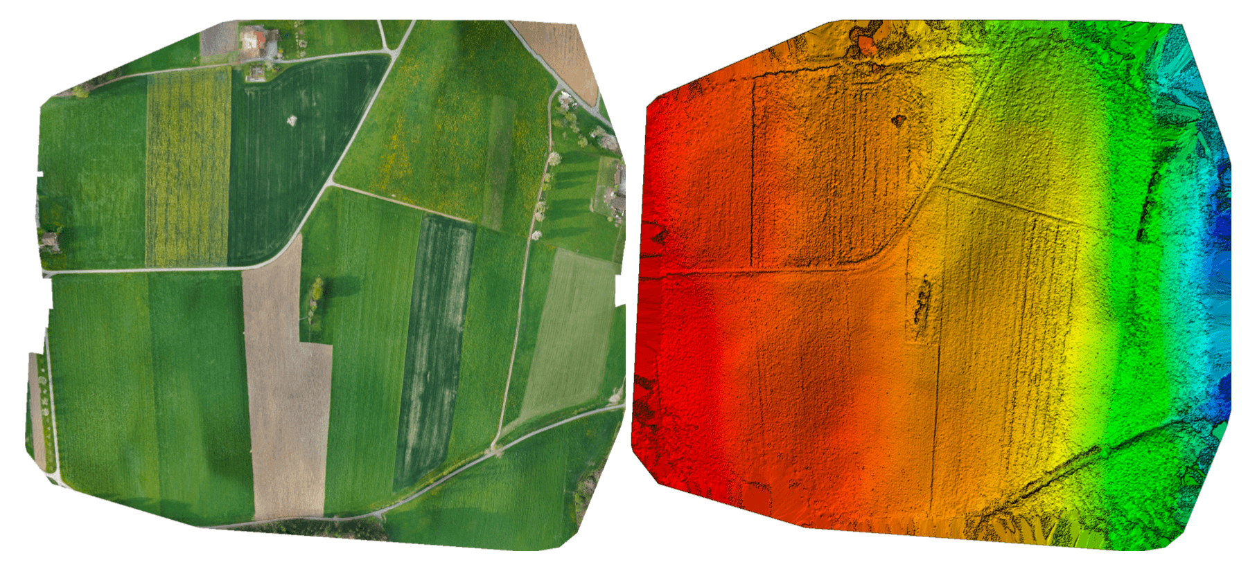
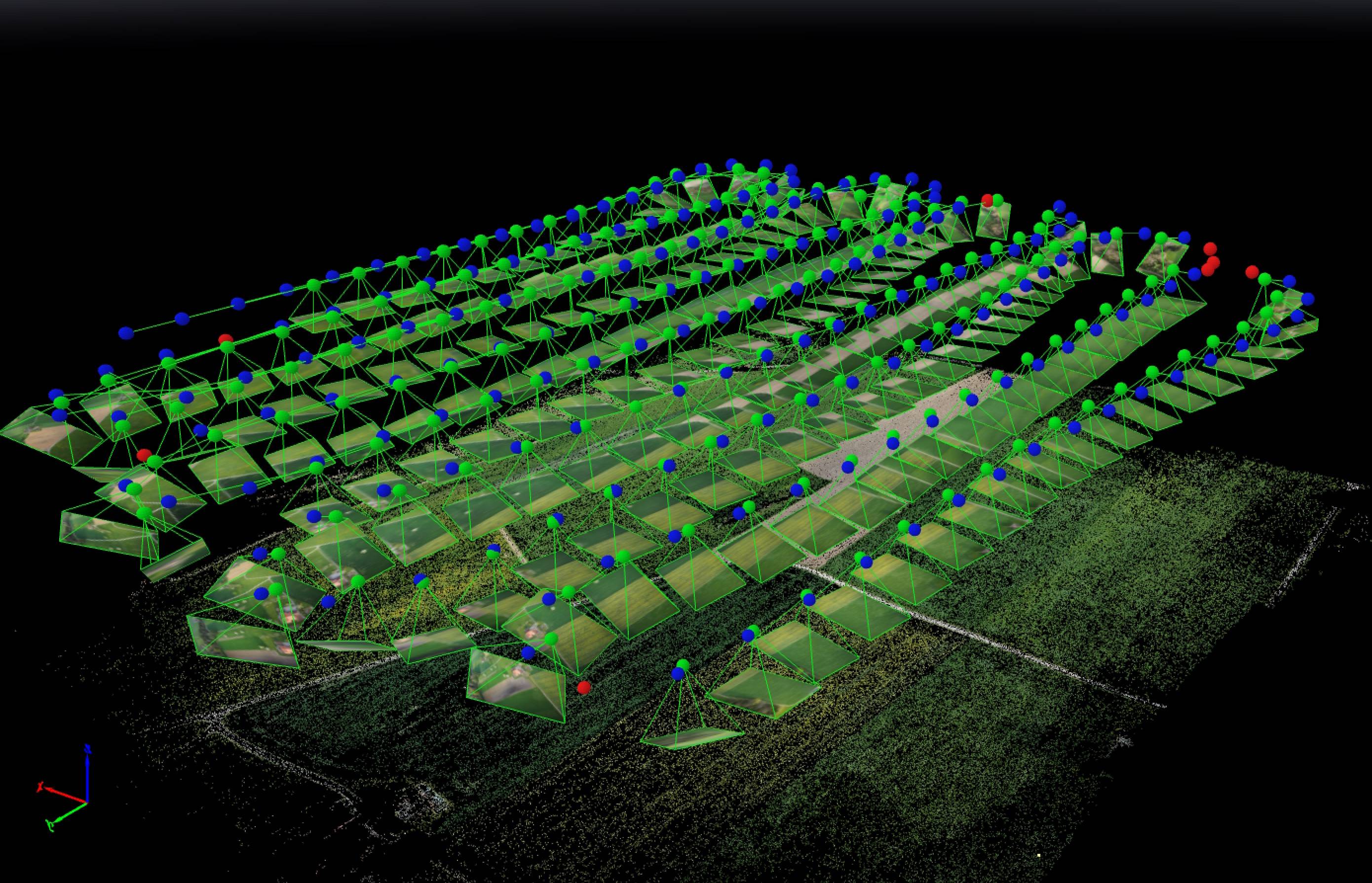
Reconstruction :
We use Pix4D for 3D reconstruction.
Camera-IMU sync example (VIO)
In this example, we will go over the basics of synchronising IMU measurements with visual data to build a stereo Visual-Inertial Navigation System (VINS). To be clear, the idea here isn't to take an IMU measurement exactly at the same time as we take a picture but rather to correctly time stamp our images so as to provide accurate data to our VIO algorithm.
The autopilot and companion have different clock bases (boot-time for the autopilot and UNIX epoch for companion), so instead of skewing either clock, we directly observe the time offset between the clocks. This offset is added or subtracted from the timestamps in the mavlink messages (e.g HIGHRES_IMU) in the cross-middleware translator component (e.g Mavros on the companion and mavlink_receiver in PX4). The actual synchronisation algorithm is a modified version of the Network Time Protocol (NTP) algorithm and uses an exponential moving average to smooth the tracked time offset. This synchronisation is done automatically if Mavros is used with a high-bandwidth onboard link (MAVLink mode onboard).
For acquiring synchronised image frames and inertial measurements, we connect the trigger inputs of the two cameras to a GPIO pin on the autopilot. The timestamp of the inertial measurement from start of exposure and a image sequence number is recorded and sent to the companion computer (CAMERA_TRIGGER message), which buffers these packets and the image frames acquired from the camera. They are matched based on the sequence number (first image frame is sequence 0), the images timestamped (with the timestamp from the CAMERA_TRIGGER message) and then published.
The following diagram illustrates the sequence of events which must happen in order to correctly timestamp our images.
Step 1
First, set the TRIG_MODE to 1 to make the driver wait for the start command and reboot your FCU to obtain the remaining parameters.
Step 2
For the purposes of this example we will be configuring the trigger to operate in conjunction with a Point Grey Firefly MV camera running at 30 FPS.
TRIG_INTERVAL: 33.33 msTRIG_POLARITY: 0 (active low)TRIG_ACT_TIME: 0.5 ms. The manual specifies it only has to be a minimum of 1 microsecond.TRIG_MODE: 1, because we want our camera driver to be ready to receive images before starting to trigger. This is essential to properly process sequence numbers.TRIG_PINS: 56, Leave default.
Step 3
Wire up your cameras to your AUX port by connecting the ground and signal pins to the appropriate place.
Step 4
You will have to modify your driver to follow the sequence diagram above. Public reference implementations for IDS Imaging UEye cameras and for IEEE1394 compliant cameras are available.